Industrial
built right first time
Our BIM expertise ensures complex industrial construction environments are fully coordinated, practical to install, and optimised for long-term operation.
-
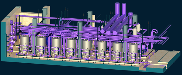
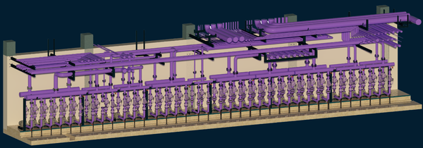
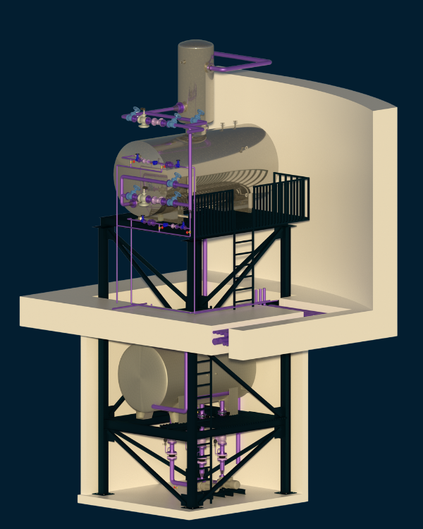
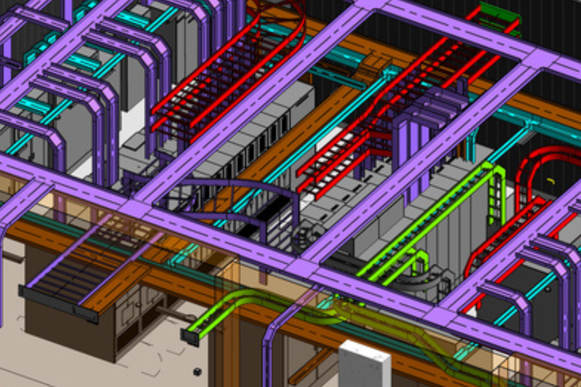
MEP systems are complex in nature and require a multidisciplined approach. Plantrooms and switch rooms have a number considerations to be coordinated with certainty and successfully.
Some Common principles applied to our plantroom coordination:
Access to components in congested areas (dampers, valves, instruments etc)
Minimum clearance zone for panels – typically 1000mm
Maintaining headroom clearance
Maintaining walkways for plant replacement strategies
Filter and component replacement clearance zones
Coordination of lifting beams (where required)
Coordination of equipment layouts and plinth construction
Shared support system (coordination of floor standing supports if required)
Verification of coordination with Vendors (if required)
Accounting for bending radius of cables into panels.
Our in-house expertise regularly design, construct, commission complex MEP systems from inception to completion. We understand the need for practical design for plant areas and getting the installation right first time.
-
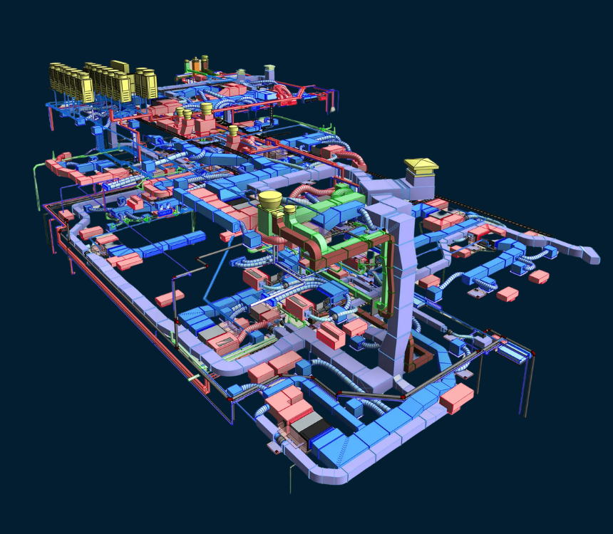
Electrical containment
mechanical services - Piping, HVAC & Equipment
Building automation
Secondary containment